How do you install a jaw coupling correctly?
Clean both shafts and the bores, insert each shaft to the full hub length given in the table, keep the specified clearance between the hub faces, check that the coupling still slides and turns freely, then tighten every screw to its specified torque with a torque wrench — never by feel.
Mounting an MJC or MJS, step by step
This is NBK’s own sequence from the MJC/MJS instruction manual, in the order the manual gives it. Budget ten minutes and a torque wrench.
Clean the shafts and the bores
Wipe dirt, dust, debris and rust from both shafts and from the coupling bores. A contaminated bore changes the friction the clamp relies on, and grit under a clamp hub is a stress raiser.
Check the shaft tolerance
NBK’s recommended shaft tolerance is h6 or h7. Outside that band the clamp cannot develop its designed holding force, and the slip torque drops below what the table promises.
Insert each shaft to the full hub length L
Use the L value for your size from the table below. NBK states the failure mode in both directions: “If the inserted amount is too short, the shaft may slip or the clamping part may break. If the inserted amount is too long, there may be shaft interference within the coupling, leading to damage.”
Position any D-cut or keyway correctly
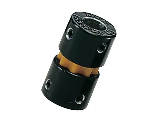
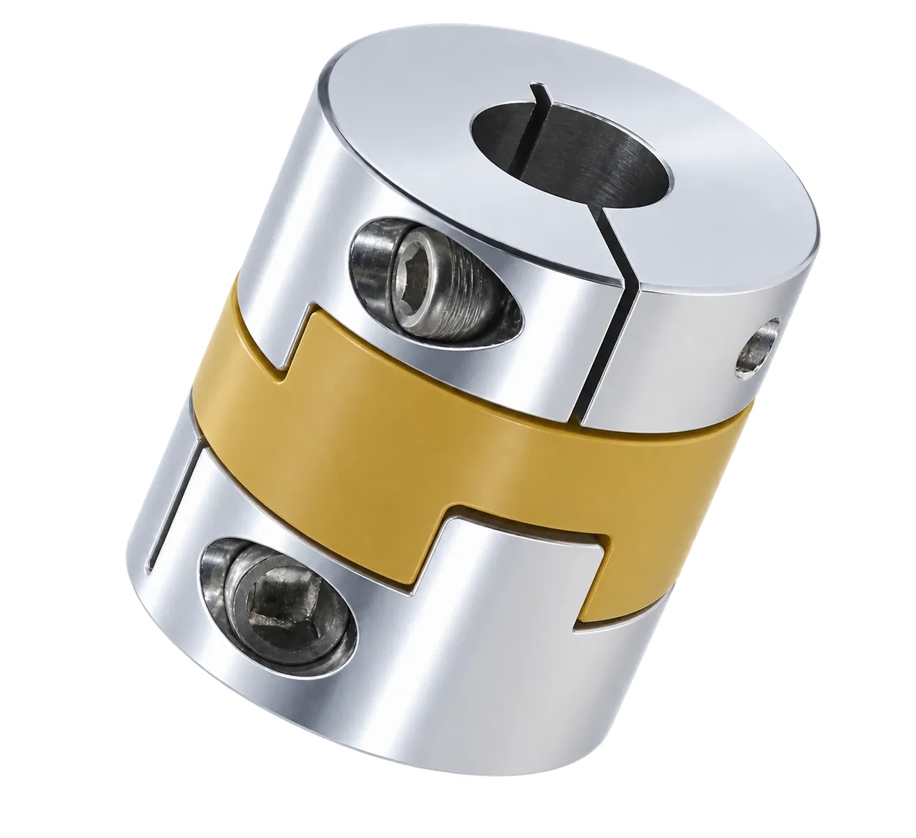
On clamping hubs, use round shafts as a rule. If a D-cut or key groove is unavoidable, turn it away from the slit and from the bolt spot facing — otherwise tightening the cap screw loads the clamp against an unsupported flat and can damage it. On set-screw hubs, do the opposite: the D-cut flat IS the seat for the set screw.
Set the clearance between the hubs
Maintain clearance C between the hub tip and the opposing hub (see table). Without it the hubs interfere in operation, and the sleeve is no longer the only thing transmitting torque.
Check it moves before you tighten
With the screws still loose, slide the coupling along the shaft and rotate it. It must move smoothly. Any binding here is misalignment or a burr, and tightening will only hide it.
Tighten to the specified torque
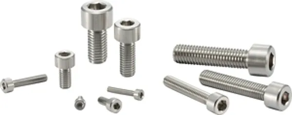
Use a torque screwdriver or torque wrench and the value from the tables below. Use only NBK’s specified screws: “Screws other than our specified ones (hex socket set screw or hex socket head cap screw) should not be used.”
Trial run, then a ten-minute load test
Run without load and confirm there is no vibration, no abnormal noise and no shaft slippage. Then run about ten minutes under load and re-check that the screws are still tight before releasing the machine to continuous operation.
Insertion depth, hub clearance and set-screw torque
| Outer ⌀ A (mm) | Hub length L (mm) | Clearance C (mm) | Set screw / torque |
|---|---|---|---|
| 14 | 7 | 1 | M3 · 0.7 N·m |
| 20 | 10 | 1 | M3 · 0.7 N·m |
| 30 | 11 | 1.5 | M4 · 1.7 N·m |
| 40 | 25 | 2 | M5 · 4 N·m |
| 55 | 30 | 2 | M6 · 7 N·m |
| 65 | 35 | 2.5 | M8 · 15 N·m |
| 80 | 45 | 3 | M8 · 15 N·m |
| 95 | 50 | 3 | M8 · 15 N·m |
Source: NBK instruction manual, MJC/MJS series, tables 1–4; cross-checked against the catalogue dimension table (p. 133–134). The jump in hub length from 11 mm (size 30) to 25 mm (size 40) is real, not a typo.
Clamping type: torque depends on the bore
| Outer ⌀ A (mm) | Bore range (mm) | Screw | Tightening torque |
|---|---|---|---|
| 14 | 3–5 / 6–7 | M2 / M1.6 | 0.5 / 0.25 N·m |
| 20 | 4–8 / 9.525–11 | M2.5 / M2 | 1.0 / 0.5 N·m |
| 30 | 6–12 / 12.7–16 | M4 / M3 | 3.5 / 1.5 N·m |
| 40 | 7.938–20 / 22–25 | M5 / M4 | 8 / 3.5 N·m |
| 55 | 9.525–28 / 30–32 | M6 / M5 | 13 / 8 N·m |
| 65 | 12.7–32 / 34.925–38 | M8 / M6 | 28 / 13 N·m |
| 80 | 19.05–45 | M8 | 28 N·m |
| 95 | 25–55 | M10 | 55 N·m |
MJC-CS/CSK and MJS-CS/CSK. The larger bore in a size uses a SMALLER screw at a LOWER torque — there is less material left around it. Source: NBK instruction manual MJC/MJS, table 5; catalogue p. 133–134.
Choosing the sleeve: BL, WH, RD or GR
The jaw coupling’s character is set by the polyurethane sleeve between the hubs, and NBK sells four hardnesses of it. They are not interchangeable, and the trade-off runs in one direction: harder sleeve, more torque and more stiffness, less allowable misalignment.
On an MJC-40, the same aluminium hubs give you anything from 4.9 N·m to 21 N·m depending purely on which sleeve is fitted — a factor of four. And the softest sleeve, which carries the least torque, is the one that tolerates the most misalignment. If your alignment is uncertain, do not reach for the hardest sleeve to be safe: you will be doing the opposite.
Sleeve hardness, measured on an MJC-40
| Sleeve | Hardness (JIS) | Rated torque | Lateral misalignment |
|---|---|---|---|
| BL | A80 | 4.9 N·m | 0.15 mm |
| WH | A92 | 10 N·m | 0.1 mm |
| RD | A98 | 17 N·m | 0.1 mm |
| GR | D64 | 21 N·m | 0.08 mm |
Torsional stiffness rises with the same ranking: 380, 570, 1,200 and 3,000 N·m/rad respectively. Source: NBK product catalogue, section “Shaft couplings”, p. 131–132.
The coupling in this article
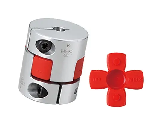
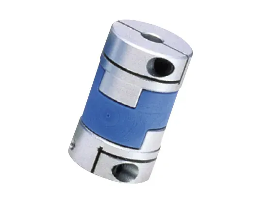
Jaw Type Flexible Shaft Coupling (MJC · MJS · MJB)
Elastomer-jaw coupling that transmits high torque while absorbing vibration and misalignment: zero backlash with tight-fit sleeves and electrical insulation.
Not sure which one your machine needs?
Send us the torque, speed, misalignment and environment. Our engineers come back within 24 hours with a concrete recommendation — and a sample if you want to test it.